When you start with your design use a blank sheet of paper and make a free hand sketch of ideas for the outline of your knife. It is not necessary to draw the outline to scale at this stage - it is more important for you to be creative in your design. Once you have drawn a design you are satisfied with your design, make an accurate drawing of the handle to scale.
Keep in mind that the blade must always be shorter than the handle. This ensures that the blade will completely fit inside the handle, shrouding the tip and thereby protecting the user when closed.
A handle of 100 to 120 mm will nicely fit most human hands. A handle length of less than 80 mm is suitable for a more delicate knife that is not intended for heavy use. The blade can be any length you choose provided that it fits within the handle - it is preferable though to rather opt for the maximum blade length that the handle would allow.
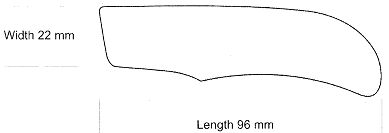
Measure the width and length of the handle that you have designed.
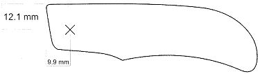
Determine the position of the pivot point. This is vitally important because many measurements that you still have to make will originate from the pivot.
The centre of the pivot is approximately 55% of the width of the handle from the top of the liner, and approximately 40 to 45% of the width of the handle from the front of the liner:
- 55% of the width 22 mm = 12.1 mm
- 45% of the width 22 mm = 9.9 mm
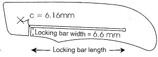
The next step is to determine the position and length of the locking bar:
- From the pivot to the locking bar's front corner ("c" in the sketch) is 28% of the width of the handle = 6.16 mm The locking bar width is 30% of the width of the handle = 6.6 mm The length of the locking bar is at least 60% of the length of the handle or longer = 57.6 or
- Fifty times the thickness of the liner 50 x 1.2 mm = 60 mm.
The length of the spring is important but not critical to the functioning of the system. The shorter the spring, the greater the force will be that is applied to the lock. The downside is however that the force required to unlock it will also be greater.
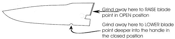
Determine where the point of the blade will rest in the closed position, taking into account the size of the back spacer or bush. We wil name this point A.
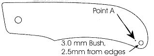
Use dividers with the pivot as centre point. Transfer point A as a radius to approximately where the tip of the blade will be in the open position. Draw the blade, not exceeding this radius line, for this will be the maximum length that your handle can accommodate.
Lay a piece of transparent film over the entire knife and draw the blade on this film. Press a needle on the pivot position and close the blade until the tip rests on the point A.
Use the transparent film to open and close the blade.

Determine point S just in front of the liner on the blade. This is where the run-out (grind line) will start and the stop-pin (the pin that stops the blade in the open position) will be in the closed position.
Transfer the notch for the stop pin drawn on the transparency to the liner.

Now draw the back of the blade and position the bushes or back spacers or bushes.
The top of the back part of your blade should be 0.5 mm longer than the actual size and the bottom of the back part or the locking part should be 2.0 mm longer than the actual size.
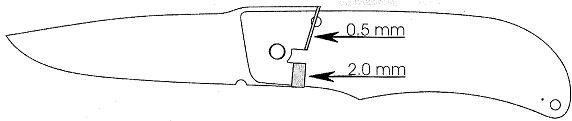
This excess will help you to align and fit the blade.
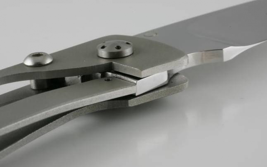
There is no inherent portion of the LINER-LOCK system which secures the blade in the closed position. For this reason a hardened steel ball bearing is positioned in the spring or lock bar to engage a detent drilled into the blade tang. This will utilize the force of the bent spring to hold the blade in the closed position.
Locating this ball detent is essential for the correct operation of the LINER-LOCK. The location of the ball bearing is determined by the dimensions of the lower radius or edge of the blade's tang.

Locating the ball bearing within the area described on the spring will prevent it from running off the blade when opening and closing the knife.
The ball should project about 0.3 mm above the spring. If the blade is to lay flush with the handle sides, the spring must be recessed into the handle plate to allow for the protrusion of the ball bearing.
Alternatively washers may be used as spacers between the blade and the handle to provide for this spacing. Washers provide a smoother operation and is therefore better to use. The washers stand the blade away from the handle plates and allow for easy cleaning of the joint. Shims or washers also avoid unsightly scratches on the blade.
When titanium is used for the liners, remember that titanium and steel do not work well together — particularly when moving against each other under pressure.

REMEMBER TO CHECK:
- That the bottom part of blade is not protruding
- That the tip of the blade is aligned with point A
- That the cutting edge clears the spacing bushes
- The ball bearing circle and hole is not visible from the outside.
To provide a lock with maximum strength, the spring on the liner should engage the blade as far below the centre line of the pivot as possible. The further below this line the spring would go, the stronger the lock up will be. Full contact between the blade and spring face is not recommended as this could cause the blade to rock up and down.

Mark out the thumb coil and bolsters. Position the holes for all the fastening screws that you will need for the handle slabs, bolsters, and bushes/spacers. Remember to take into account the diameter of the screw heads you will use to assemble the finished knife. Do not place the holes to close to the edge of the handle - you will need to chamfer the finished handle and you don't want that chamfer to touch the screw holes.
It is now time to transfer the drawing from the two dimensional representation to a three-dimensional object.
- Make a couple of photocopies so you will not have to cut up your original drawings.
- Cut out the complete blade section from one of the photocopies and a complete handle section from the other.
- Spray the back of each with spray glue and fix them to a piece of scrap metal plate or Perspex. Then cut out the profiles on a band saw.
- Drill out the pivot holes on both the blade and the handle patterns and assemble them with a try pin.
- Open and close the blade — if it works sucessfully this is your template.
Now cut out all the parts you will need:
- Blade
- Liner
- Liner with spring bar
- Two bolsters (to fasten this you will need four round-headed screws)
- Two handle slabs of your choice of material for the handle (four round-headed screws)
You will also need:
- pivot screw
- stop pin (2.4 mm hardened steel dowel)
- two bushes or back spacers plus two countersunk flat head screws shims to cut out two washers for pivot pin
- bearing ball 1.58 mm diameter